Minima
The Minima is an amateur radio transceiver designed by Ashaar Farhan.
In October 2014, I gave a presentation on the Minima at Pacificon. You can look at the slides and handouts and download an audio recording.
Characteristics
Its main characteristics are:
- General coverage: 0 to 30 Mhz
- Single Side Band modulation and CW
- Output power of about 1 W with the original amplifier (more on that later)
- The frequency is set by a Si570 Digitally Controlled Oscillator
- An Arduino-style micro-controller is used to control the front-panel and drive the oscillator which makes the entire project very easily hackable
Links
If you are interested in this project:
- Join the Minima mailing list (Subscription form at the top of the page)
- Read the official Wiki for the Minima and Radiono (the name given to the software)
- Take a look at Mark G0MGX blog. He has lots of great articles on building the Minima.
My minima
I was looking for a first home-brew project when Farhan announced the Minima and ended up being one of the early builders of this project. I am using this page to share construction notes in the hope that they will help future builders. I bought the first parts and started building on january 24th 2014 and listened to my few QSOs on feb 27th.
Building and Testing the crystal filter
I used an Arduino connected to a AD9850 DDS board to generate an input signal and characterize the crystal filter (source code of my signal generator). I did not have the equipment to characterize the crystals properly so the selection was just random.

I started taking notes on paper and quickly moved to Google Spreadsheets:

Lessons learnt
- How to properly measure RF power with an Oscilloscope
- The importance of 50 ohm impedance matching
- How to measure the output impedance of a generator
- Building a LC network to do impedance matching
- 50 ohms termination
References
The Minima group was super helpful and pointed me in the right directions for a lot of basic RF knowledge that I was lacking:
Winding my first toroids
I got myself an AADE L/C Meter to measure the inductance of the toroids I am winding. For $100 you get a very nice kit to build in one quick evening including front panel, buttons and decals. The enclosure is pre-cut and drilled, you just have to solder. This little instrument has an excellent reputation in the ham radio community and is super useful.
Don’t buy one of the cheap LCR meters on Amazon or eBay, most of them cannot measure anything smaller than a few nano-farads or micro-henris. We work with much smaller values in RF.
Winding the toroids is not very fun but it is pretty easy. I have found toroids.info to be a great resource. It will tell you how many turns you need on your cores and what is the approximate length of magnetic wire you need.
For reference, these are the values Mark used and mine:
| Value | Qty | Core | N-Turns (Mark) | N-Turns (Thomas) |
|---|---|---|---|---|
| .33 uH | 2 | T37-6 | 10 | 9 |
| .39 uH | 2 | T37-6 | 11 | 10 |
| .66 uH | 2 | T50-2 | 12 | 10 |
| .78 uH | 3 | T50-2 | 13 | 11 |
| 3 uH | 3 | T68-6 | 25 | 24 |
| RFC | 3 | FT37-43 | 25 | 24 |
Building the Low pass filters
Glued the toroids in place Soldered the toroids and then adjusted inductance before locking them with nails-polish Used qrpme mepads


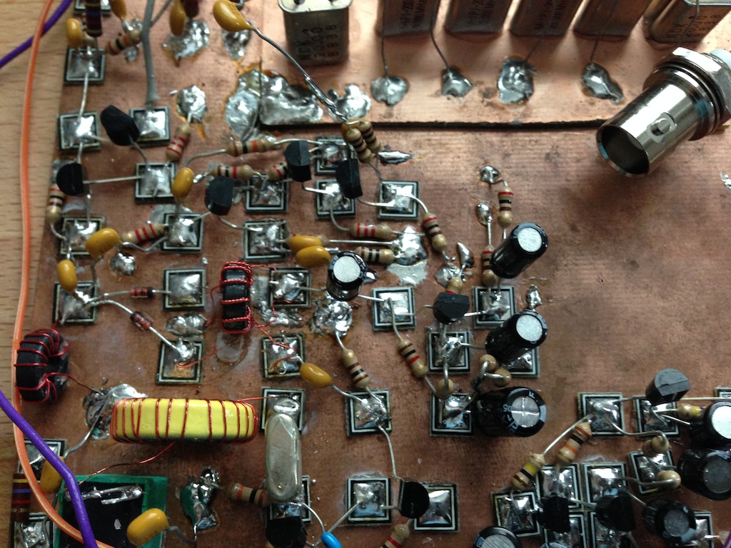
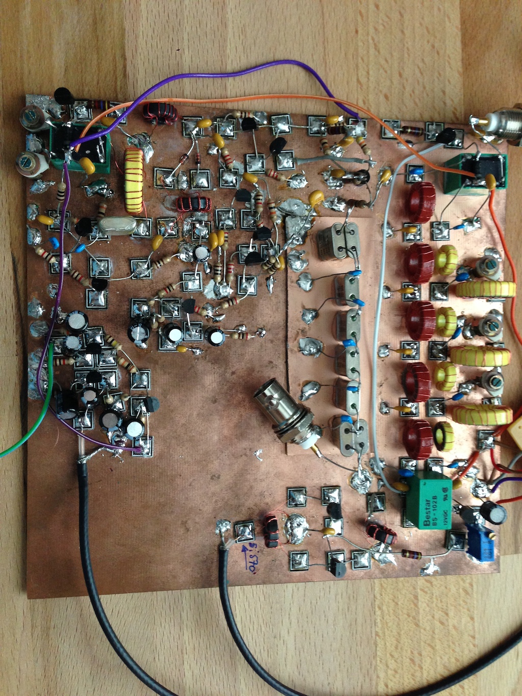
Building the main board


Calibrating the oscillator
When I first started my Minima, the output frequency was far from spot-on:
I did some research and made a pull-request to solve this problem:
You still need to tell the software what is the factory calibrated frequency of your Si570
Building the KISS Mixer
Make sure you wind those transformers really well. Use a drill to wind the three wires into a trifilar winding. I have tried lots of other methods but trust me, a small drill with a hook is the best solution.
You will not be able to adjust the bias of the two JET transistors now. Don’t worry about it.
Building the BFO Mixer
Followed Farhan’s instructions to match the diodes. I used my Fluke high-resolution mode (0.1 mV) which was probably overkill because I realized after having measured 20 diodes that just blowing on them or touching them would change the reading by several millivolts.
If you can get them to match at +/- 1 mV, you should consider yourself very happy!

Building the RF pre-amp
Nothing special here. Just a bunch of transistors. I did manage to get the last output resistor wrong (22 ohms instead of 220 ohms). I was wondering why that last transistor was heating so much … I realized my mistake when a few days later the resistor started getting brown…
Building the BFO


Building the Audio pre-amp

Building the Audio amp
Used an LM386

Debugging the minima in RX
When I put everything together, my Minima showed very little sensitivity. I could hear a strong signal that I injected from a VFO in the antenna - or even another emitter a few meters away but I could not get any real signal and the band were awfully quiet. It did not sound like a “receiver”.

I went through each stage, measured gains, checked bias on the transistors, compared with other builders, rewound my transformers 3 times, etc.
Long story short: I had misplaced one capacitor in the BFO. Instead of putting a 100pF between Q9 base and emitter, I had put it between the base and the collector. The result is that the BFO signal was much less stronger that it should have been.
Once I fixed this:
I had to play around with the BFO frequency to be able to listen to signal. More work to do there!
Playing with a spectrum analyzer and the crystal filter
I have secured access to a spectrum analyzer (the usual suspect: rigol dsa-815-tg). I have done some basic experiment with it including one with my cristal filter. With almost 6kHz bandwidth, it’s probably going to be a bit too large and I will have to re-work it a little bit.
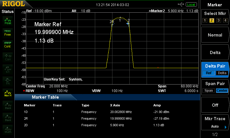
My initial measurements were not incorrect but I had an “optimistic” way of guess-timating where the 3dB bandwidth fell. The spectrum analyzer is more deterministic…
Building the TX stages and boxing the Minima
I added the TX pre-amp and the Mic pre-amp.
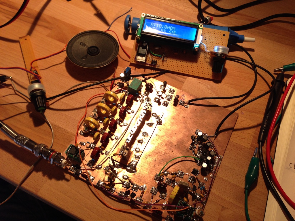
With everything on the board, it is starting to get crowded:
I don’t really do CW at the moment but I decided to include the CW tone generator anyway. There is a lot of fun stuff we could do with Arduino + CW. Next piece is the RX/TX relay and the few transistors that go around it. I have decided to keep my LM386 amp for the moment. It has been doing a great job.
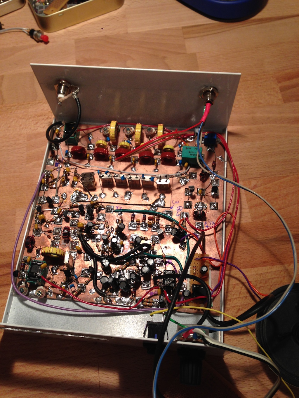
Finally I did some metal work and wired all the control signals between the Minima and the RF Board.
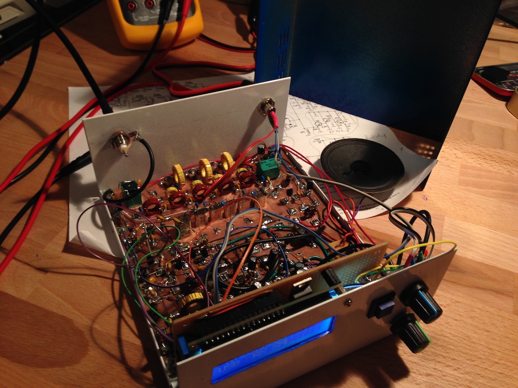
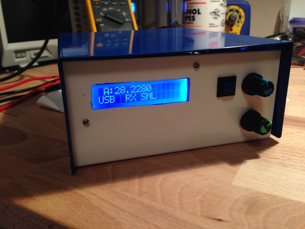
My Minima is almost complete: Need to get some audio jack for a microphone input, a headphone jack and a CW key input. I would also like to wire the PTT on the Mic jack. More on that later.
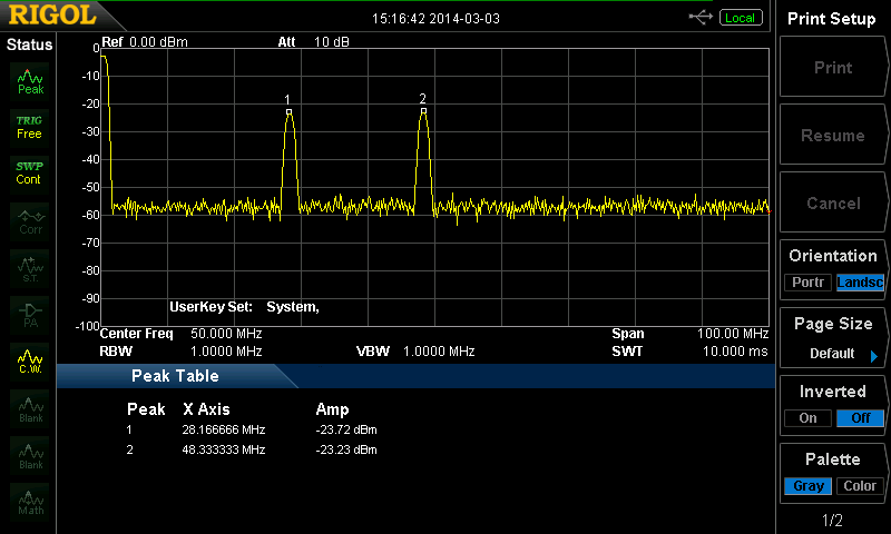
At the moment my Minima is stuck in transmit but this is a known problem (you need an external pull-up resistor on the PTT line). I will add this soon. I had not done any real testing of the TX stages so I just plugged the minima in the SA and looked at the output.
This is what a 28.200 Mhz signal modulated with the CW tone looks like. The peak at 48 Mhz is the local oscillator and it should be much more attenuated. I will look into this.